ROME - Routing Over Mobile Environment
This document introduces ROME, a geographic routing protocol for wireless sensor networks (WSNs) with mobile nodes. It first gives some background about ROME, its objective and its operation. Then the hardware resources and software environment to install ROME are described. After illustrating how to install the ROME demo application, it briefly explains how to run this routing solution.
Table of Contents
- ROME - Routing Over Mobile Environment
- Introduction
- Objectives of ROME
- Installation
- ROME Demonstration
Introduction
Experiments on real-hardware testbeds, have shown that even if the nodes in WSNs are static, the network exhibits high dynamics because of the instability of communication links and the disappearance of some of the nodes due the depletion of their energy and to their failure. New nodes can also be added to the network at any time, which also causes variable network connectivity. Furthermore some of the sensor nodes could be mobile, being worn by humans, carried by animals, or mounted on mobile robots and vehicles.
Objectives of ROME
ROME innovation provides the SENSEI architecture with an energy-efficient multi-hop connectivity function for WS&AN islands. Specifically, it is possible to send interest requests to the nodes in the island through a SENSEI gateway, and collect sensed data. The protocol is energy efficient, as it addresses the energy constraints that are typical of devices in WS&AN islands. Each node in the island follows an asynchronous duty cycle (e.g., it is awake the 10% of time, while it is asleep in the remaining 90% of time) so that energy usage is balanced in the network. Besides energy efficiency, the major distinguishing factor of ROME is its ability to rapidly adapt to changing network topologies, ensuring WS&AN connectivity also in presence of nodes mobility and addition/removal.
Installation
Hardware and Software Requirements
Installing the ROME protocol requires the following hardware tools and software packages:
- Linux PC (Ubuntu)/ Windows XP
- JAVA SE jdk-6u21
- TinyOS-2.x
- ROME demostration binary package
We assume that the installation PC is running a Linux operating system, and the TinyOS-2.x and JAVA environment have been installed and configured properly. We skip the installation of TinyOS. A user could refer to TinyOS-2.x for an installation guide.
Software setup
In order to route data packets ROME requires the position of each node of the WSNs. This position, which could in future come from a GPS unit, are now statically stored in a file. Each node is unique localized by its (X,Y,Z) coordinates with respect to a fixed point. Note that these coordinates do not have necessarily to be in an absolute reference system (like GPS) but also relative to a certain point.
The file to be included in the project needs to have this format :
#define N_NODES_TESTB	27
uint8_t positions[N_NODES_TESTB][3] = {
	{50, 55, 8},	//
	{48, 55, 8},	//
	{50, 51, 8},	//
        ............
};
Each node has an element in the above array with index set equal to the node's TOS_NODE_ID. In case this could not be achived it is always possible to implement a mapping layer for the requirents SOME_NODE_ID_POLICY->TOS_NODE_ID translation
For what it concerns mobile nodes the same observations apply. At the moment the mobility is implemented throught a static data structure which mime the position the mobile node would be in next steps. A file with the moves log needs to be filled and then parsed with the script generateMobilityInclude which eventually transform the raw position data into a file compileable by TinyOS.
An example of mobiliy data position follows:
NODE 3:
(0, 0, 0)
(20, 0, 0)
(20, 20, 0)
(0, 20, 0)
;

NODE 6:
(10, 0, 0)
(10, 10, 0)
- define the mobility pattern for each node in a data file. Coordinate must be specified in 3-d format. Paths can have arbitrarily length up to uint8_t max size.
- run the python script generateMobilityInclude.py to parse the mobility pattern data file. The script will generate an header file MobilityPatterns?-AUTOGEN.h, containing pattern definition.
generateMobilityInclude.py MOBILITY_PATTERN_FILE
- rebuild the ROME application
The sink node requires a bit more attention. The ROME Makefile needs to specifiy the TinyOS TOS_NODE_ID of the sink node. This is achived with the compile time define
#define ROME_SINK_NODE 81
The installation of ROME is rather easy and the following brief introduction shows how the ROME resource could be loaded into the nodes.
- First of all, a user needs to install and configure TinyOS-2.x and JAVE Environment jdk-6u21 properly.
- Then the user compile the ROME application.
make telosb
- Install the compile firmware into the nodes.
make telosb reinstall.<node ID> bsl,/dev/ttyUSB*
ROME Demonstration
The following description is about how to run the ROME demo application and how to test whether it is installed properly. For sake of semplicity we developped a reduced number of nodes demo which requires just 5 nodes. We also set a virtual topology up in order to show some ROME characteristics. In goes without saying that the demo application could be re-arranged on a larger network with some extra effort
Nodes setup
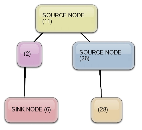
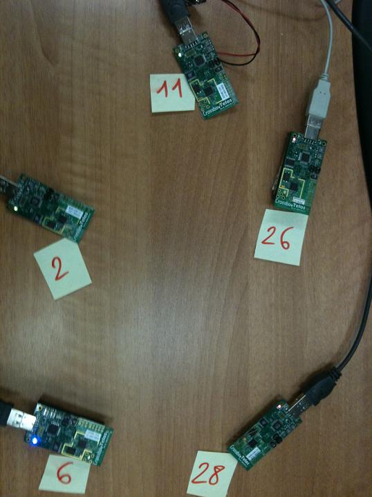
The demo application requires a set of 5 sensors and builds up a virtual topology as shown in the topology graph image, where as two nodes (11, 26) will be sending data packets towards the sink (6), two nodes will simply act as relay agent (2,28).

Demo objectives
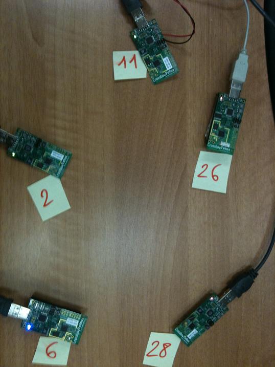
The demo shows some aspects of the ROME capability of preserving connectivy. In the demo the node 28 changes its color from green to red when it figures out it has no positive route towards the sink. As conseguences of this change also the node 26 will have to change its color from green to red for the very same reason.
Operation
- First, turn on all normal nodes, except the sink. Please note that after a node is powered on, its green led will be turned on indicating it has a possible data route towards the sink node
- Turn on the Sink node.
- The blue LED off the sink node is turned on
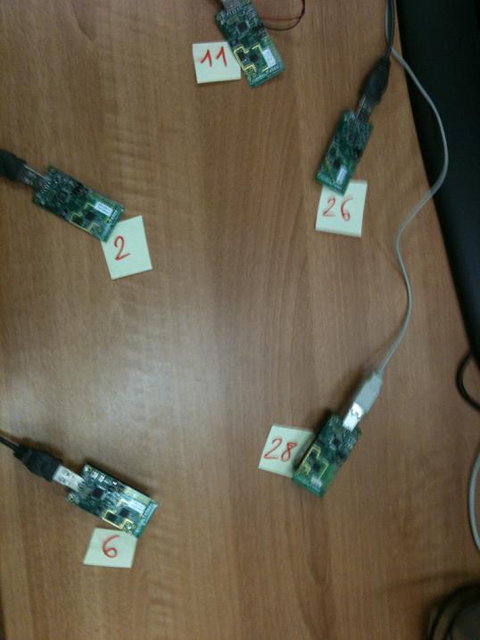
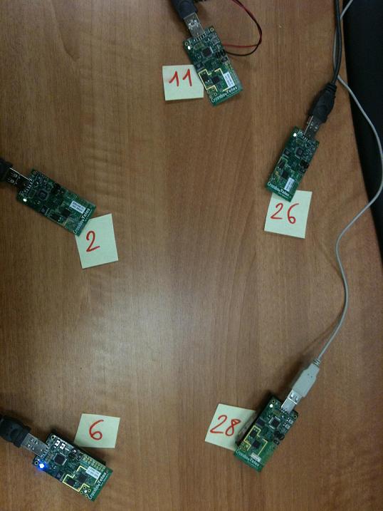
The next shows the testbed at startup where all nodes, but the sink, have greeen led turned on. The sink node has the blue led on.

Let's now see how the ROME protocol react to connectivity isseues. The node 28 has not positive route toward the sink because topology is built up so to create this constraint. In the left picture it is possible to see that the node 28 has turned its state from green to red as displaied by the new led state. As a consequences of this the node 26 needs also to update its state to red because it has now no more relay agent towards the sink. The network is now in its final state


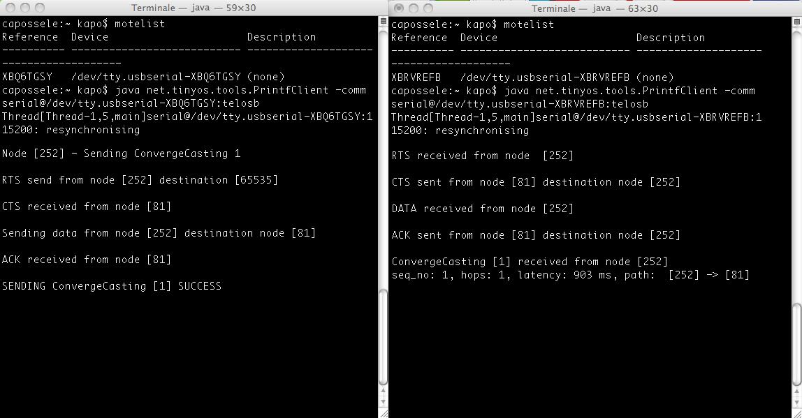
Monitor the debug messages
A user is able to use the serial output to watch the debug messages:
# java net.tinyos.tools.PrintfClient -comm serial@/dev/ttyUSB*:telosb
The debug messages should start to be shown in the terminal as following.
Output from sink
Output from node 26
Output from node 28
Attachments (8)
- cookbook1.png (33.2 KB) - added by 13 years ago.
-
virtual_topology.jpg (43.8 KB) - added by 13 years ago.
Virtual topology graph
- 1-testbed.jpg (44.3 KB) - added by 13 years ago.
- 2-start.jpg (55.5 KB) - added by 13 years ago.
- 3-colorChanged-node28.jpg (50.7 KB) - added by 13 years ago.
- 4-colorChanged-node28+26.jpg (53.7 KB) - added by 13 years ago.
- 5-final.jpg (51.9 KB) - added by 13 years ago.
- fig1.JPG (57.7 KB) - added by 13 years ago.
Download all attachments as: .zip